Home » Explore » Locomotives & Rolling Stock » Locomotives » Steam Locomotive Controls - Steam Locomotive Controls
Steam Locomotive Controls
Let's take a look at the controls in a Great Western steam engine cab and find out what they do. The controls on G.W.R. engines were pretty standardised by the 1920s. If you look in the cab of a Castle class express passenger engine or a Pannier tank shunting engine, there are a few differences, but not many.
We'll take a virtual tour of the cab of a Great Western Railway tender locomotive, mainly using photos of No. 4079 Pendennis Castle.
The Fireman's Side (left)
We are going to draw a line down the middle of the backhead or the rear section of the boiler. Whilst not 100% accurate, the vast majority of controls on the left are for the fireman and on the right are for the driver. There are also controls on the tender too. These are all pretty much the province of the fireman as well. The large coal area and the water tank that surrounds it are self-explanatory as is the water gauge on the left as we look back.
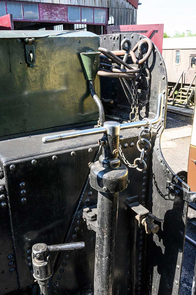
4079's handbrake and water scoop, with the gauge showing level of water in the tank behind it
There are two large handles on pedestals. The one on the right is the handbrake and there is a chain next to it. The chain is only put on the handle of the brake is on. It’s a good visual indicator and reminder. On the tender engines, only the tender has a handbrake. The loco wheels are only braked when the engine is in steam. The other large handle is the water scoop. This winds down a mechanism that was used for picking up water from troughs that were strategically placed at points on the main line. This meant the engine could pick up water on the move – about 3,000 gallons in a ‘scoop’! The two little handles are the water valves that turn the water on and allow it to flow in pipes towards the locomotive.
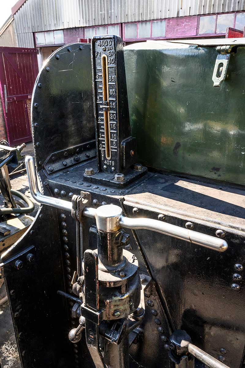
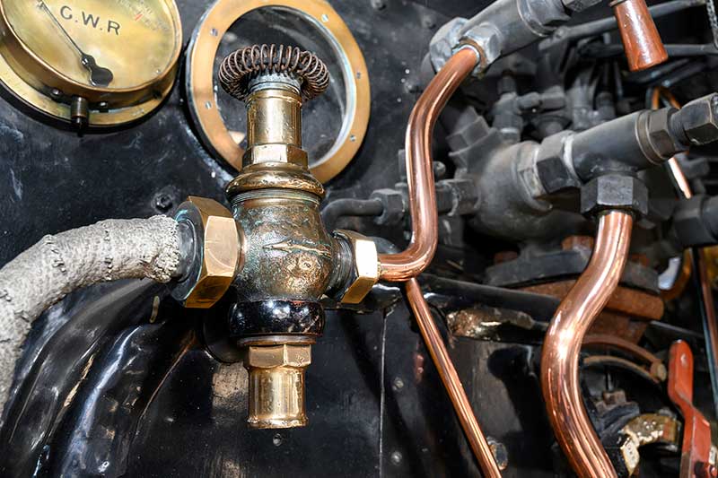
One of 4079's water valve handles and 4079's steam fountain, with the mason's valve on left
If we turn back to the locomotive, we can see that on top of the boiler, there is a large casting with all manner of taps and valves coming out of it. This is known as the fountain and it is where the steam for almost all of the auxiliary services on the engine. Most of the little valves are shut off cocks for the various systems. On the far left of the fountain, we start with what is known as the mason's valve. A tall brass casting with a wound wire handle. This is the pressure reducing valve for the steam heating for passenger coaches. The lagged pipe that leads down to the floor takes the low pressure steam to the train.
5322's mason's valve kept beautifully polished
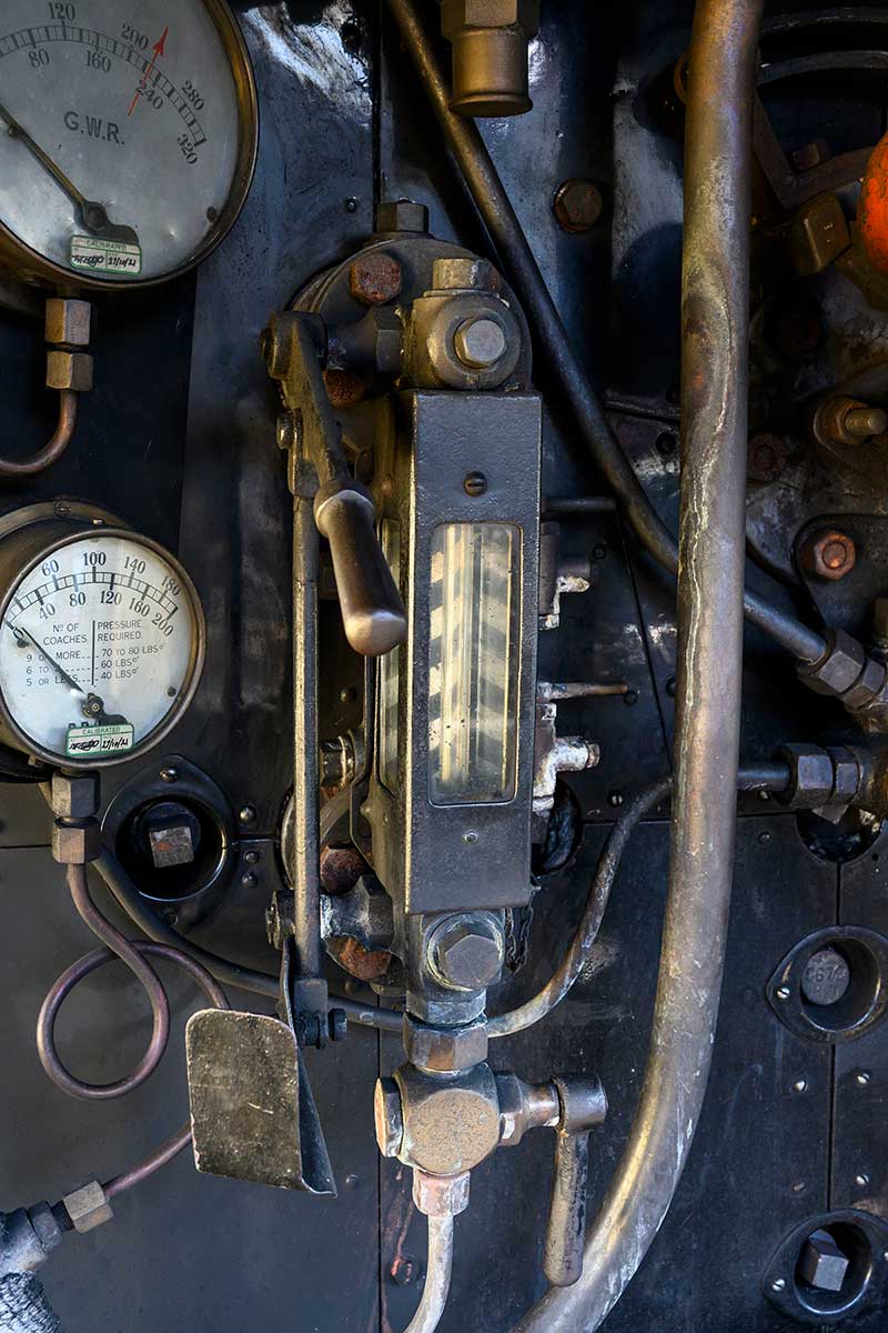
4079's gauge glass protector. The gauge on the left is for steam heat pressure to the train, controlled by the mason's valve.
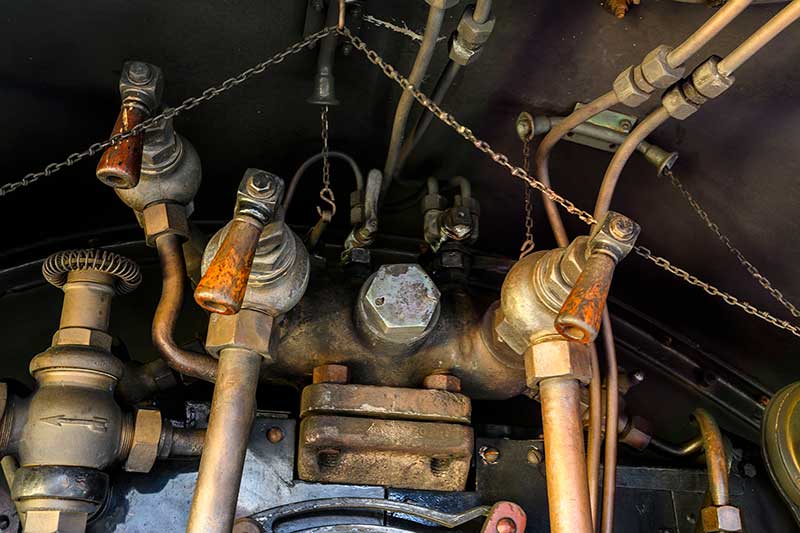
On the front of the fountain are either two or three large spherical valves with large bore pipes leading down to the floor. These, in combination with the tender water valves, are the feeds to the injectors. These get the water from the tender and past the boiler pressure into the boiler. How much water do you need to put in? Look no further than the gauge glass. This is the vertical glass tube in a glass box. The box – the gauge glass protector – has two functions. It provides protection for both the glass itself and the crew. It stops the glass tube from being broken by the crew accidentally and, if the gauge glass were to fail, it prevents the fast moving bits of glass from the resultant burst of steam from getting to the crew. There is a linkage on the side with a handle and this turns the gauge frame on and off. The little handle below it is the drain so you can empty it.
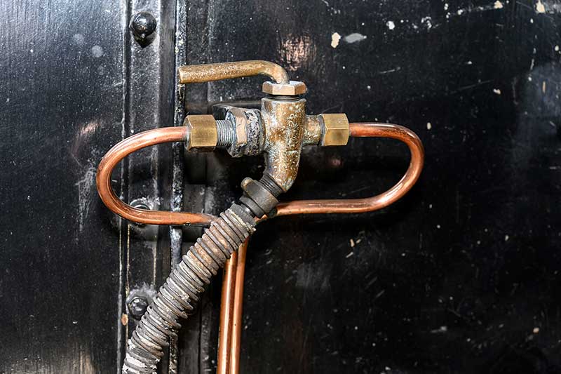
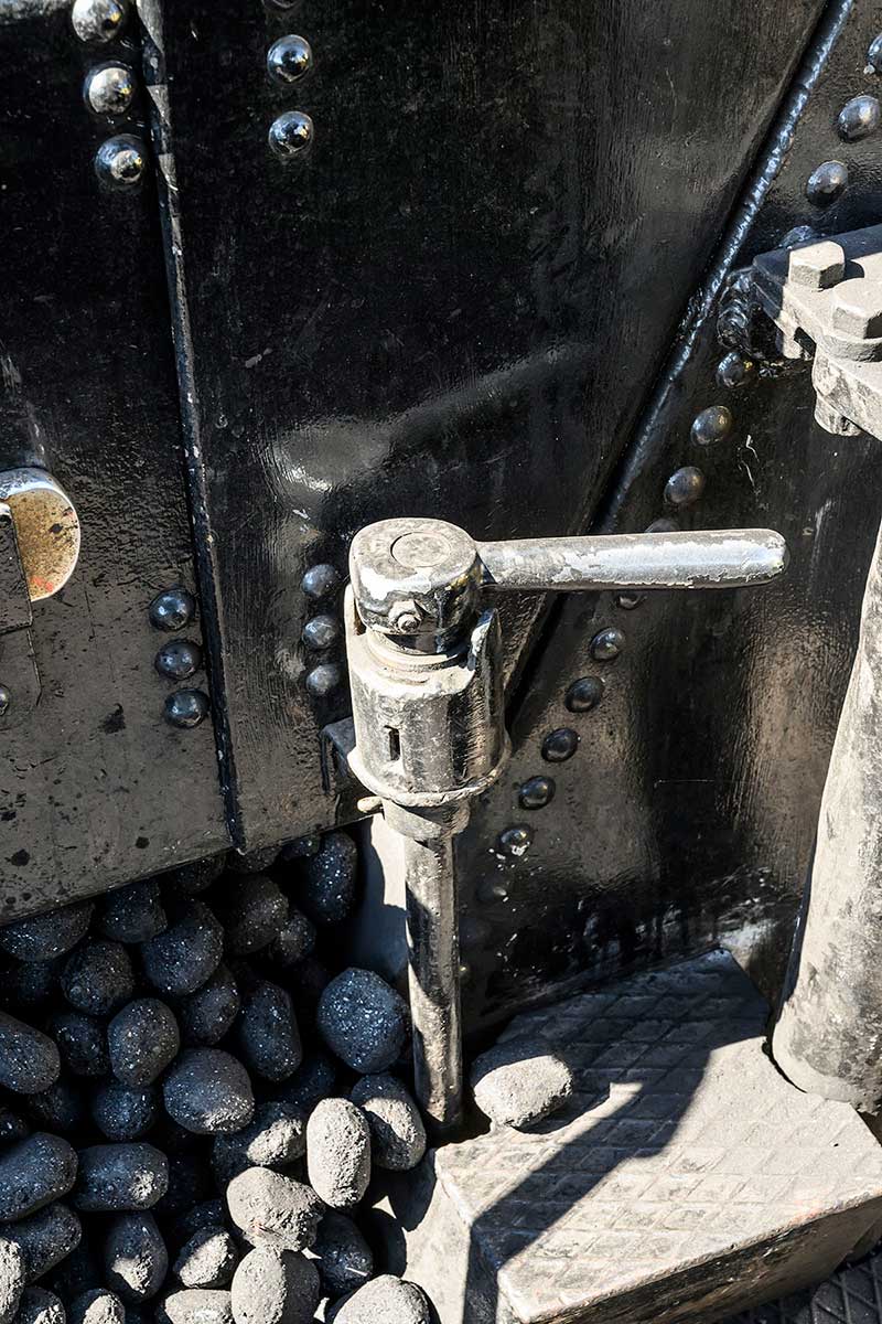
The pep pipe control on 5322.
All steam engines legally need two methods of reading the boiler water level. Most British locomotives have two gauge glasses, however, the Great Western Railway had to be different! The two large taps behind the gauge frame are called the test cocks. If you open them and water comes out, there is water there. If you open them and steam comes out, the water level is below that point. If it is below the level of the bottom one, you then put your injectors on as your boiler is very close to being too empty! Under the fireman's seat, is a small valve for the pep pipe. This is the hose that the fireman uses to hose down the cab to keep it clean and damp the coal to prevent dust. The pep pipe operates when the fireman's side injector is turned on.
220624_4079-damper-handles.jpg)
The four damper handles on 4079
In the floor, there are 4 handles. These operate flaps on the ash pan and are known as the damper doors. By operating these, you can control the airflow to the underside of the fire. There are four on GWR 4-6-0s as the lower section of the ash pan is split in half by the rear driving wheel axle. So the handles, left to right, are front front, front rear, rear front, rear rear. Confused? You will be! The not yet mentioned elephant in the room (cab?) is the fire hole door.
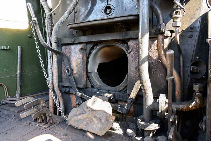
4079's firehole doors and flap. The damper handles can be seen on the left
There are two methods of closing it up. The first is the use of the large cast iron doors and the linkage and lever. This is quite heavy to operate so you will also notice that there is a steel flap on a hinge with a chain. This can be quickly and easily opened and closed by the firemen if they are working with the fire. Doors for longer periods shut, flap for brief. It basically helps the firemen conserve their energy.
And they do need their energy. The longest fireboxes on GWR locos are 11 to 12 feet in length. When firing, the fireman has to get the coal to exactly the right place. It's not just a case of fling it in! Holes in the fire draw cold air up the riveted joints and stays of the boiler. Being cold in one spot and hot in another causes the plates to twist and this can make leaks occur. Which annoys the boilersmiths and can be expensive… Oh, and if the engine is working hard, a big loco like a King or a Castle will consume fuel at the rate of up to 1 ton per hour. On that one shovel, in the right place, at the right time, on a footplate that will be bouncing around at anything up to (in steam days) 100mph+.
Whilst they are managing the water levels in the boiler and keeping the fire hole door fed, there is another job for the firemen. They need to use the windows. Strange as it may seem, the signals were on the left side of the cab and the driver was on the right. So, the fireman was an extra set of eyes for the driver too. They were a very skilled breed. They were also very busy.
The Driver's Side (right)
The most obvious control in the driver's arsenal is the large red lever in the middle of the backhead. This is the regulator, the steam locomotive equivalent of the accelerator in a car. The amazing thing about this is that the control is at one end of the engine and the valve it operates is at the other end! The regulator valve is in the smokebox. This can be a long way from the cab in the larger locomotives. Being creatures of the machine age, they are connected together in the most simple manner possible. A huge rod. You can see the far end of it in the middle of the regulator handle. It goes through a steam tight joint (or gland), passes all the way along the inside of the boiler and connects into the regulator valve at the far end.

4079 regulator
The valve itself is actually two valves sort of laid on top of each other. The first part of the arc when you open the regulator opens a smaller valve called the pilot valve. When this reaches its fully open position, this in turn starts to open the second larger or main valve. With the handle pointed up ‘into the roof’, you have regulator fully open. With it pointed to the floor, the regulator is fully shut.

4079 jockey valve
Connected to the regulator is a linkage that operates a valve underneath it. This is known as the jockey valve. This supplies steam to the hydrostatic lubrication system via the condenser coil.

4079 condensing coil
There is a separate blog on this in the archive but simply put the big coiled pipe in the cab roof allows the steam to condense back to water but it remains at boiler pressure. This is forced into the big brass box near the driver's seat. This pressurises the thick oil that is forced up through pipes to the valves, regulator and cylinders up the front end.

4079 lubricator
The controls on the front of the brass box are little taps below small sight glasses. These control the speed at which the oil drips and is fed into the system. It is quite usual to see a piece of white paper stuffed behind the glasses to make the drips easier to see. It's usually yesterday's timetable at Didcot…

4079 blower valve
Above that are a collection of valves. The one on its own, with a spherical body, is the blower. This sends a jet of steam through a circular ring and up the chimney. This lowers the air pressure in the smokebox, gives an artificial draught through the boiler tubes and pulls fresh air into the fire – just like the exhaust does when the loco is working. It is used to stop air being forced back down the chimney when the engine goes under low bridges or into tunnels. If you think about it, a sudden blast of air down the chimney would force the fire out of the fire hole and into the cab. This could turn the cab interior into a blast furnace. With good training this is thankfully very rare. A blow back, as it is known, would not be a great situation to be in…

4079 brake valve, with vacuum gauge top right
Above that is a circular valve with a wooden handle sticking out of the top of it. This is the brake handle. The little holes in the face being where the air is let into the system to destroy the vacuum and apply the brakes. There are two other handles, one small and one large, and these operate the ejector. This is the device that creates the vacuum for the brakes and I really ought to do a blog on vacuum brakes as it’s a bit too complex to fully go into here. Above this lot is the vacuum gauge and there are two needles on the face. The right one shows the vacuum in the reservoir and the left, the vacuum in the train pipe. Think of this as the brake line and this vacuum is the one that pulls the brake off. 25” of mercury - brakes off, 0” of mercury - brakes fully on.

6023 speedometer
Moving to the stuff under the window, the use of the speedometer is obvious! The big lump with the mangle type handle is known as the reverser.

6023 reverser, showing cut-off scale 0 to 75 per cent
In car terms, it's a bit like the gearbox. No actual gears are involved however! It all done with the valves above the cylinders and the valve gear. With the indicator in the middle, the engine is in mid gear or neutral. Wind the indicator all the way forward and it will be alongside the 75% cut off mark. This means that for every stroke of the piston from one end to the other, steam is being let into the cylinder for 75% of that distance. This is the steam engine equivalent of first gear. If you left it here as you accelerate, the boiler would soon empty of steam and you would have an angry fireman on your hands!
Thankfully as you accelerate, you need less steam to keep you going. So, you slowly wind the reverser back. At 80mph on flat ground, a King of Castle with 10 - 12 coaches would be in about 20 - 25% cut off. The equivalent of fifth gear in a car. The cool thing about steam engines is that they work just as well forwards as backwards and the reverser has 75% cut off for both directions! The only limit was the tender. Fine if being pulled but a bit ‘lively’ if being pushed fast. Usually tender first workings were limited to 45mph.

6023 ATC
The box with the bell is the Automatic Train Control. This is an amazing safety system that was in another of my previous blogs – it is a truly fascinating system and worth looking at.
The last few controls are in the floor. The lever with the ratchet is the cylinder drain cocks and these are the valves that are used to clear the water out of the cylinders.

4079 cylinder cocks lever
There are two other levers – one that operates fore and aft and the other that operates side to side. These are the sanders. They open and close valves in the sand boxes to drop sand onto the rail tops to improve traction in slippery conditions. The fore and aft lever does the forward sanders and the side to side, the reverse sanders.

4079 sander levers
The theory of all of this is actually fairly simple and you can learn the basics quite quickly. However, the art of driving and firing is a very different kettle of fish indeed and doing it well is a task that can take a lifetime to achieve. In fact, it took a 14 to 15-year-old boy cleaner almost an entire career to get to the top link driver’s seat. The men that drove the Kings and Castles on the crack expresses were the most experienced men available.
40+ years old was usual for these top link drivers. Screaming along the GWR main line with 13 coaches behind you, closing in on 100mph, in charge of a mass of metal and humanity weighing well over 600 tons was a huge responsibility. Not one to be taken lightly. It may sound like an epic undertaking but dozens of express trains like these left main stations all over the UK daily in the age of steam. These men performed their jobs largely unseen by the general public, battling the elements of fire, air, earth and water and coaxing their mighty iron horses to perform to their limits. Keeping people moving and the wheels of commerce and industry turning…

Swindon drawing showing arrangement of cab fittings on a Saint class locomotive
 |
 |
 |
 |
Didcot Railway Centre Newsletter
Stay up to date with events and what's going on at Didcot Railway Centre.
You may unsubscribe at any time. We do not share your data with 3rd parties.