Home » Other Articles » Going Loco Index » Going Loco - September 2023 - Going Loco - September 2023
Going Loco - September 2023
FRIDAY 29 SEPTEMBER
A Communication (About) Breakdown
The recovery of vehicles that have parted ways from the rails was a feature of railways from the beginning. From the very earliest days, the cast iron rails literally broke under the weight of these new-fangled kettles on wheels. Blocks, levers and eventually jacks were employed as technology progressed but eventually the engines and rolling stock became so heavy that some sort of mobile crane would be the way forward.
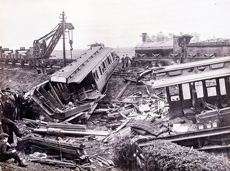
In the aftermath of the Loughor accident on 3 October 1904 a hand-operated crane is in place to assist in clearing the line
There were travelling cranes that were used by the railway to lift goods on and off wagons or for civil engineering projects from the 1850s. These were hand powered affairs and the first record of one of these being specifically built for recovery of railway vehicles was one made for the Great Northern Railway in 1853. This was hand powered and had a capacity of eight tons. Steam power had to wait until 1875 when Appleby Brothers built five examples for the Midland Railway. They were mounted on a four-wheel chassis and had a five ton capacity. From there the capacity and size of the cranes grew and grew as technology progressed.
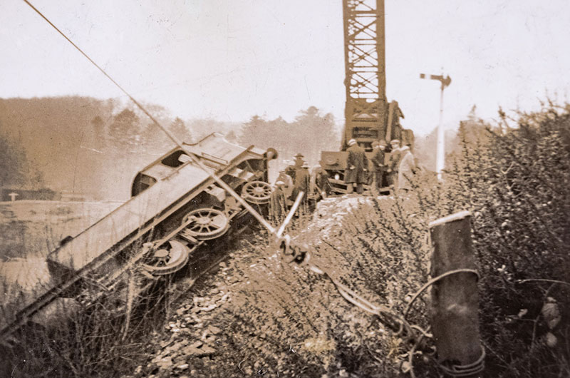
The derailment of 2-6-2T No 4402 at Yelverton on 25 January 1939 is a tricky problem for the crane sent to lift the locomotive
The Great Western Railway was slow in the uptake of steam powered breakdown cranes and didn’t have any until it ordered three from Cowans Sheldon in the very early 20th century. They were of fifteen tons capacity. Then, they went all in and ordered cranes of increasing capacity all the way up to 36 tons by 1908. The pace of development of locomotives meant that ever stronger steam cranes were needed and cranes were now reaching 50 tons in capacity as WWII loomed on the horizon. Just as well as the devastation caused by air raids meant that they were needed to keep the railways running.
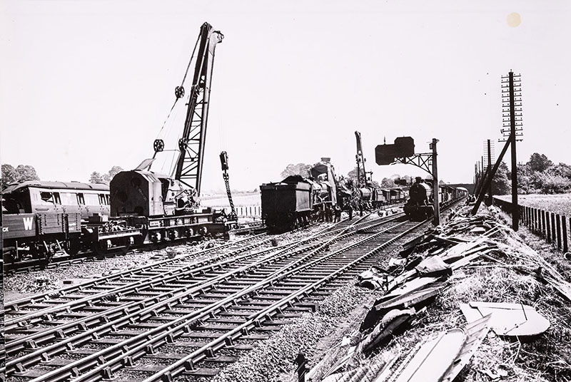
Breakdown cranes at Slough on 2 July 1941 after a Plymouth to Paddington express hauled by No 4091 Dudley Castle was crossing from the main to relief lines and collided with a westbound goods train hauled by LMS 8F class 2-8-0 No 8283 which was on loan to the GWR
The dawn of post war Britain brought with it nationalisation and eventually modernisation. Surprisingly, steam held on here longer than it did on trains as it was a known and understood technology. Many old cranes were replaced with new models and 75 ton versions were now produced. The steam cranes continued on into the late 1970s but the changing face of the railways as well as other methods of re-railing vehicles meant that the breakdown crane was a technology with a limited lifespan. The conversion of the large 75 ton steam cranes to diesel power actually extended the lives of the smaller steam cranes as they deputised for their more powerful brethren. This meant that a lot more of them got preserved. Remarkably a steam crane lift on the national network was performed as late as August 1989! Obviously, the use of a mobile crane for the early steam preservation movement was a really good idea. As such many of these cranes continue to have a home and some are still in use in this capacity.
Which is a neat link to get us to our steam crane! Ours is one of the few members of our collection that is not of GWR origin. Crane No RS 1054 was built in 1930 by Cowans Sheldon. It was ordered by the London, Midland and Scottish Railway as a 36 ton capacity machine. At one end of the crane section is a large counterbalance weight and the boiler. There is then the mechanism for driving the various features and somewhere for the driver to stand. Then, out the front, is the huge jib.
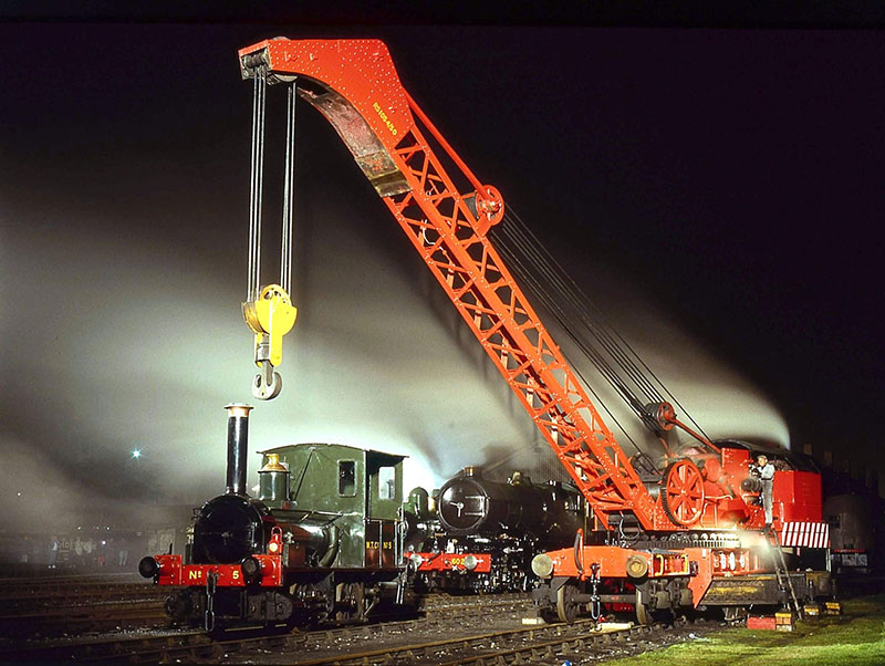
The 50 ton steam crane in action at Didcot in October 1993
It looks a bit like a train of vehicles in its own right and this is because it isn’t just the crane itself. This is mounted on an eight-wheeled rigid frame. The turntable for the crane is mounted on top. There are then two four-wheeled weight relieving bogies at either end of the main vehicle. These were invented by a Mr Wilfred S Stokes* in 1904. As cranes got bigger, they got heavier. The rigid frame of the crane ‘chassis’ can only have so many wheels under it and even then, the weight of the vehicle is still the weight of the vehicle. If it is too heavy to go down the secondary routes, branch lines and into the sidings then its usefulness was limited. This changes if you spread the weight over even more wheels. The Stokes bogies have a mechanism that links the three vehicles together and acts like a sort of flexible bridge, that distributes the weight while the vehicle is being moved. A jack is used to take the weight on and off. If the crane needs to be pushed closer to the accident, the bogies can be removed by the crane job and placed to one side.
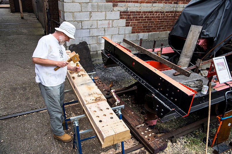
The buffer beam of jib runner No RS 1054 being replaced during restoration
It also has a jib runner. The jib on these cranes is really long and sticks out a long way from the main body of the crane. We need it to have something to rest on so that the vehicle that is coupled up to it can have a set of buffers and a coupling to do so! The runner on No. RS 1054 has an ‘A’ frame on it that is topped by a sliding roller. This means that it can move about as the crane goes through the corners of the track. It also has a pocket below it to hold the hook and its sheave** which is quite a massive thing! Whilst the crane was delivered to Motherwell in Scotland new as a 36 ton unit, it was uprated later on to become capable of lifting 50 tons and in this form it lasted for a very long service life. Its final posting was at Haymarket near Edinburgh and from here in the early 1980s, it came to the attention of the Great Western Society.
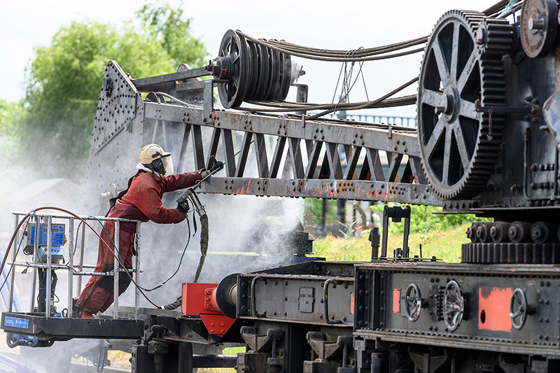
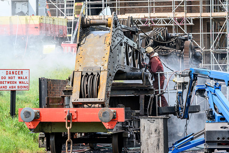
The jib of the 50 ton steam crane being stripped of paint by a high pressure water jet in May 2022
It comes complete with Beam Wagon No ADB 741583. This vehicle carries the spreader beam that means that chains on the end of the hook can be spread out to provide several even lifts at the same time. This is nowhere near as old as the crane and was constructed by British Railways in 1957. Also of BR origins – 1951 this time – is demountable tank wagon No ADB 749039. This was provided to extend the time the crane can operate in the veils. Being a steam crane, it needs water. The likelihood of the accident the crane is attending having a suitable water source is pretty low. The tank simply extends the supply.
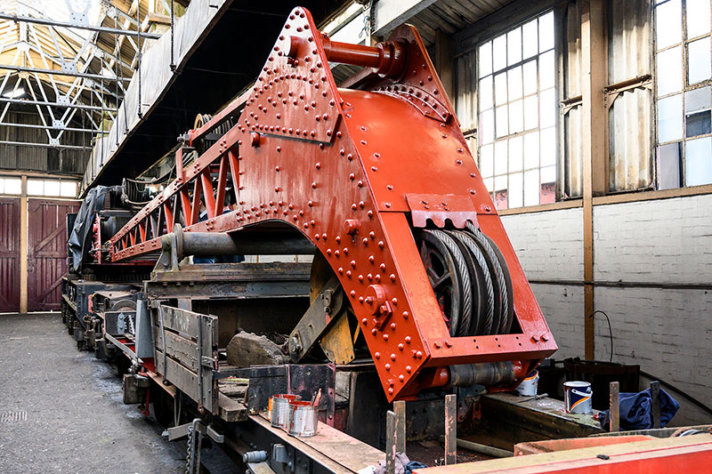
The jib resting on the jib runner, after a protective coat of primer paint was applied
There is currently a small team lead by Steven Tomsett who are working hard to return No RS 1054 to operation. The long term aim is to have a complete demonstration breakdown train with all the vehicles described above and breakdown tenders as per GWR practice.*** The team have already restored Beam Wagon ADB 741583 and are currently starting to restore their way from one end of No RS 1054 to the other. They are currently making great progress with the jib runner.
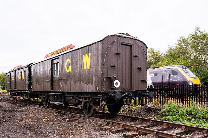
Breakdown train riding van No 56 and tool van No 1, both built in 1908
The aim of the project is twofold. Firstly, the crane in the lifting shop is fine if you can a) bring the vehicle to the crane and b) lift the thing you want to lift high enough. Which is a problem when you want to a) overhaul our broad gauge engine Fire Fly or b) take the boiler out of the steam railmotor. You can see the issues .…
Secondly, the ability to demonstrate these things working is a fantastic thing for members of the public to come and see. Imagine special ‘Operating Breakdown Crane Days’! It should add an extra element to that working museum thing we do and also be good fun as well! As always, the application of time, money and enthusiasm is required to make this happen. We’re not short on the enthusiasm!
* The same Mr Stokes that invented that WWI favourite, the Stokes Mortar. I like the weight relieving bogies better – less explosions.
** Sheave or pulley.
*** Follow the link to my blog called Wonderful Winter Wagons – The Emergency Services to find out more about these fascinating vehicles:
FRIDAY 22 SEPTEMBER
Have A Brake ….
It’s surprised me looking back that we hadn’t touched on this fairly important subject before. When you get hundreds of tons rolling down the track, it’s a really good idea to be able to stop it .… To that end, let’s take a brief look at this somewhat complicated subject. Our collection has four distinct types of brakes present, each with their own intricacies.
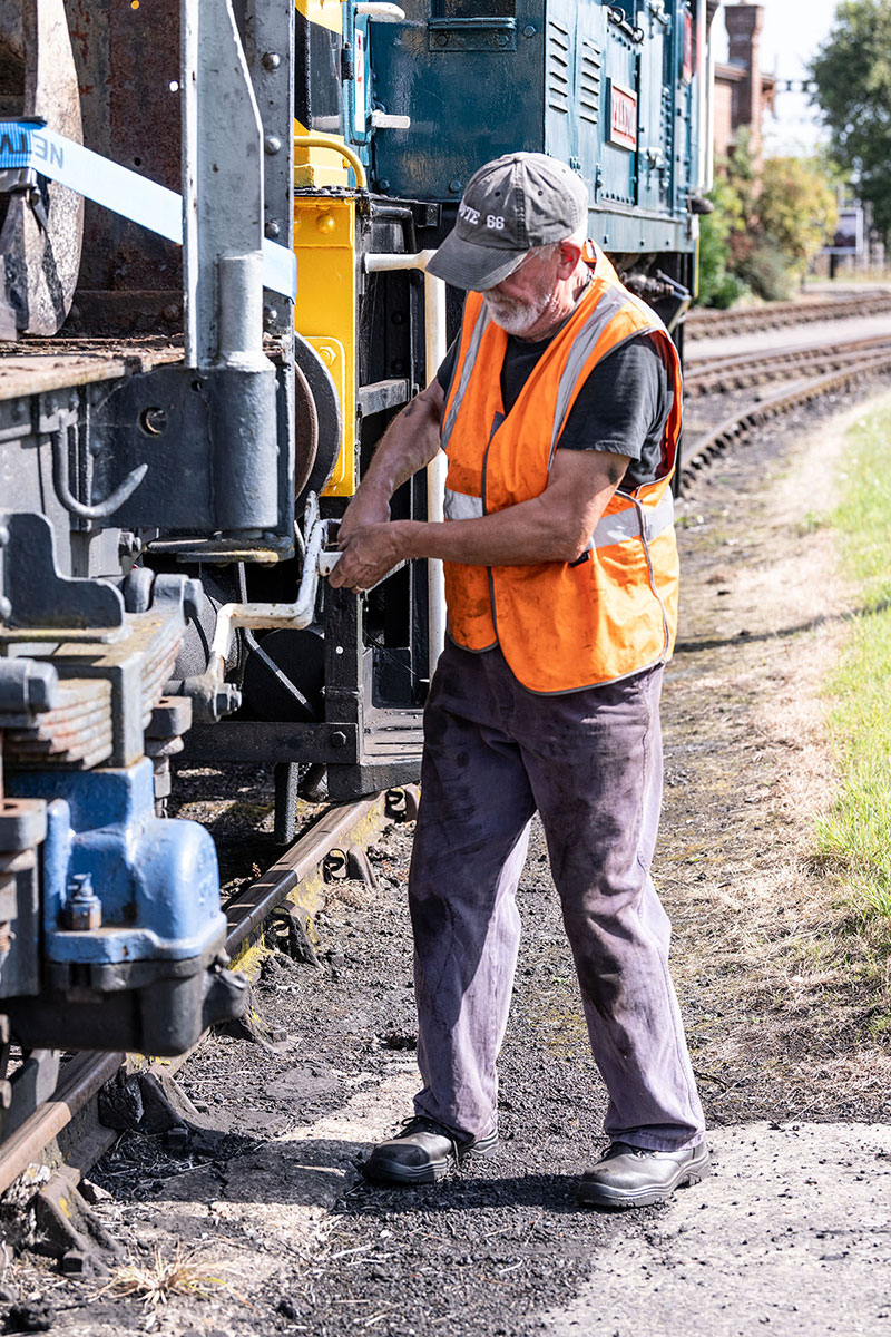
Applying the brake on a wagon by pushing the lever down
Hand brakes are the simplest and most common type of brake to be found on the vehicles on the collection. These are brakes that are operated by either a lever of some kind or a screw. Those on wagons tend to be of the lever type and those on coaches and locomotives are of the screw type. The idea is simple, some sort of mechanism is moved to press brake blocks against the tyres of the wheels to stop them moving.
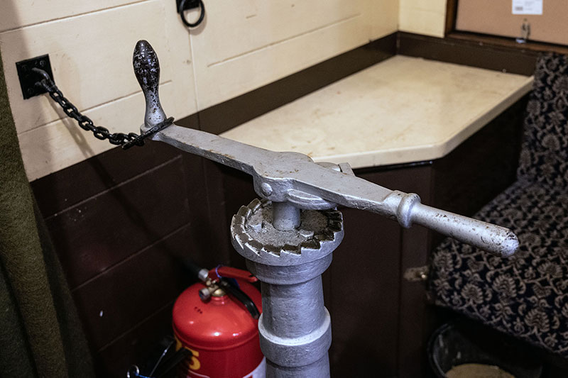
The handbrake screw in Travelling Post Office No 814
Many wagons in the steam era were what is termed ‘unbraked’, meaning that there was no brake on board that was operated by the controls on the locomotive. They did have a handbrake to stop them rolling off when parked though! Some coaches don’t have handbrakes but anything with a guard’s compartment has a handbrake. Locomotive handbrakes can be put on with a screw handle. The only thing of note here is that tender engines only have a hand brake on the tender and not on the locomotive. As they are permanently coupled, this isn’t an issue!
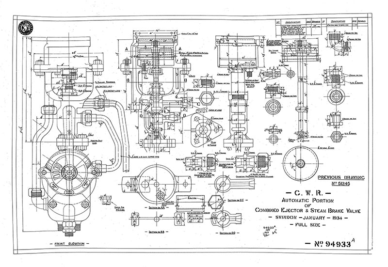
A drawing of the combined ejector and steam brake valve fitted to pannier tanks and other smaller locomotives. Original drawing in the archive at Didcot Railway Centre
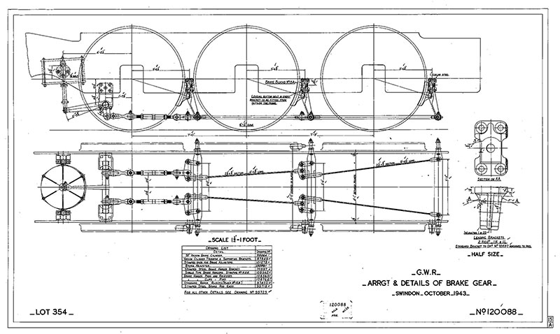
The arrangement of brake gear on a County class 4-6-0 locomotive. Original drawing in the archive at Didcot Railway Centre
Steam brakes are found on locomotives and are exactly what they sound like! They are a cylinder with a piston inside, acted upon by steam pressure from the boiler. They are not fitted to all types of locomotives however. They tend to be the province of the smaller engines. For example, locos that would not be expected to be hooked up to trains with continuous braking* for any sort of reasonable distance. Shunting engines like No 2409 King George, No 1340 Trojan and No 1338 are great examples of this. They were all built as shunters, possibly moving wagons from one yard to another in a very local area would be about their limit. As such, the steam brake is essential as it would be their only powered brake. The panniers (Nos 3650 and 3738) have a combination brake that operates both the steam and vacuum brakes in unison. Larger engines are solely vacuum braked.
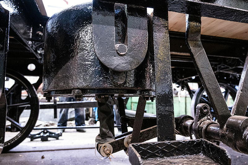
The vacuum brake cylinder fitted to Mica B refrigerated meat van No 105860, now under restoration
It became a legal requirement in 1889 that all trains carrying passengers were to be fitted with what is known as a continuous brake. This means three things. First that the brake should be capable of being applied on every vehicle on the train. Secondly that either the guard or the driver should be able to apply the brake. Finally, should the train become divided – a coupling fails – it should cause the train to stop. You can’t do this with steam brakes for a multitude of reasons but if you change your working fluid to something based on air then you stand a chance!
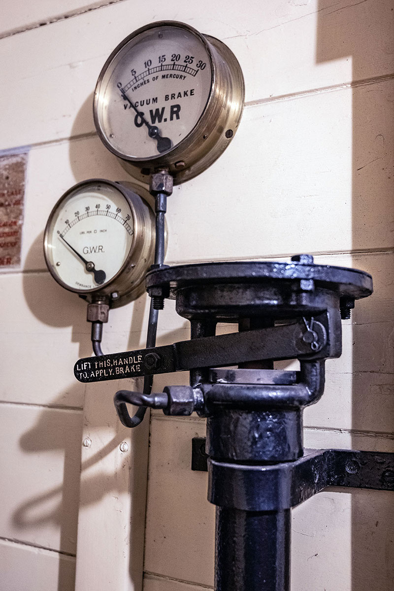
The brake setter in Travelling Post Office No 814
The solution for the vast majority of steam era Britain was vacuum brakes. In its most basic form, you have a large diameter cylinder with a large space above and below the piston. When the brake is on, the top of the piston has a vacuum applied to it and the bottom has normal air pressure applied. This pushed the piston up and, through a linkage, pulls the brake blocks on to the wheels. When the bottom and the top both have equal vacuum applied, the piston will sink to the bottom of the cylinder and the brakes come off. The vacuum is far easier to deal with than high pressure steam and can easily be transmitted along the length of the train. The simple act of letting air into the system pulls the brakes on, so it fails to a safe mode.
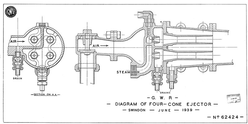
A drawing of the four-cone ejector. Original drawing in the archive at Didcot Railway Centre
So, it the guard has a handle in his compartment (called the setter) that he can lift up to let air in, the train stops, a similar arrangement but a bit more controllable is used in the cab and if the flexible vacuum pipes between vehicles split, air gets in and the train stops. To make the vacuum, a device called an ejector is used that uses the Venturi effect of accelerating air in a cone or four with the use of steam, draws the air behind it along and creates the vacuum. The Great Western Railway used 25 inches of mercury of vacuum in their brakes** and so used an air pump powered by the motion of the engine to keep this up. It’s the characteristic tick, tick sound you hear when a GWR designed engine is coasting along without power. Our steam shunters previously mentioned have had some vacuum brake equipment fitted by us to allow them to pull passenger trains.
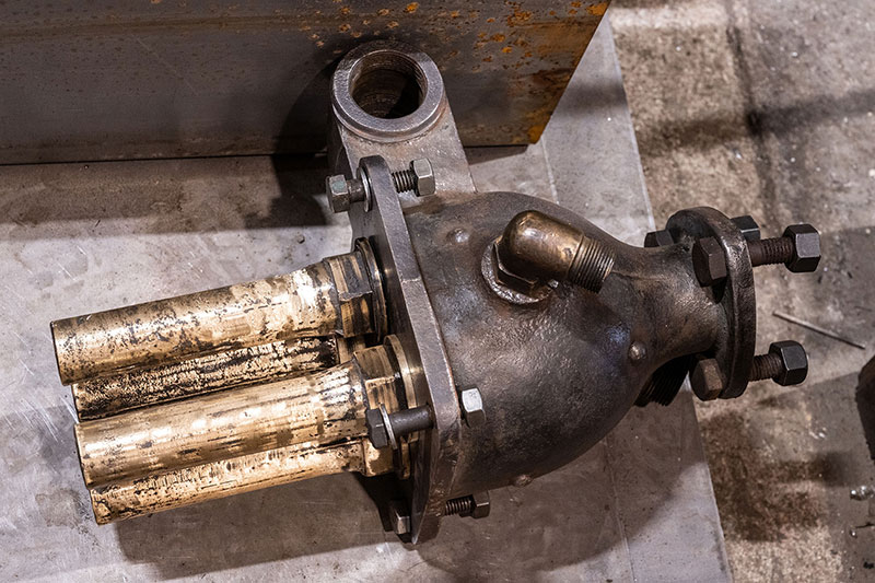
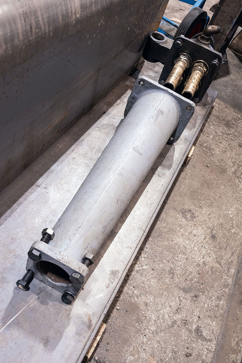
Components of the four-cone ejector to be fitted to No 1014 County of Glamorgan at Didcot Railway Centre
The vacuum brake is all but extinct on the modern railway and this is due to the use of the air brake. Despite the fact that the majority of UK steam used vacuum brakes, the air brake was invented way back in 1896. There were parts of the British system that used air brakes but it was only post-modernisation and the end of steam that it took over in its entirety. Needless to say, we find this system on the diesels in our collection and on the wagons that are main line registered to take goods to and from the west yard as we have no direct road access.
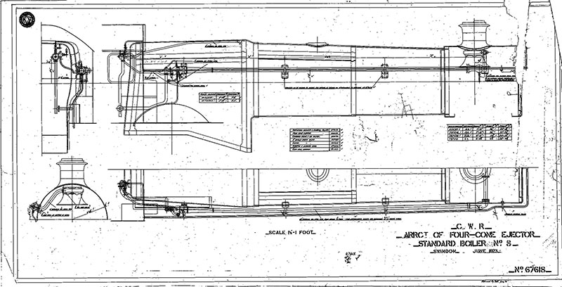
A drawing showing how the four-cone ejector is fitted to the boiler. Original drawing in the archive at Didcot Railway Centre
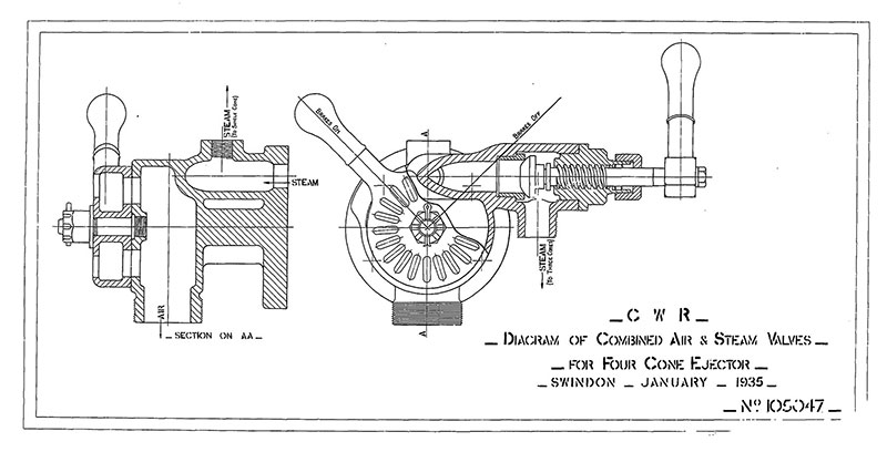
A drawing of the combined air and steam valves fitted to larger locomotives. Original drawing in the archive at Didcot Railway Centre
This system uses air pressure to do pretty much what the vacuum did. Low pressure on one side and high on the other moves the brake shoes against the wheel and air pressure in equilibrium means the brakes come off. It’s a lot more complex than that but that gives you the idea. Instead of working at 25” mercury vacuum, these systems have reservoir tanks charged to about 125 to 140psi although the pressure in the train pipe is lower than this. A clever system of valves means that a graduated application can be made and held or taken off if needed.
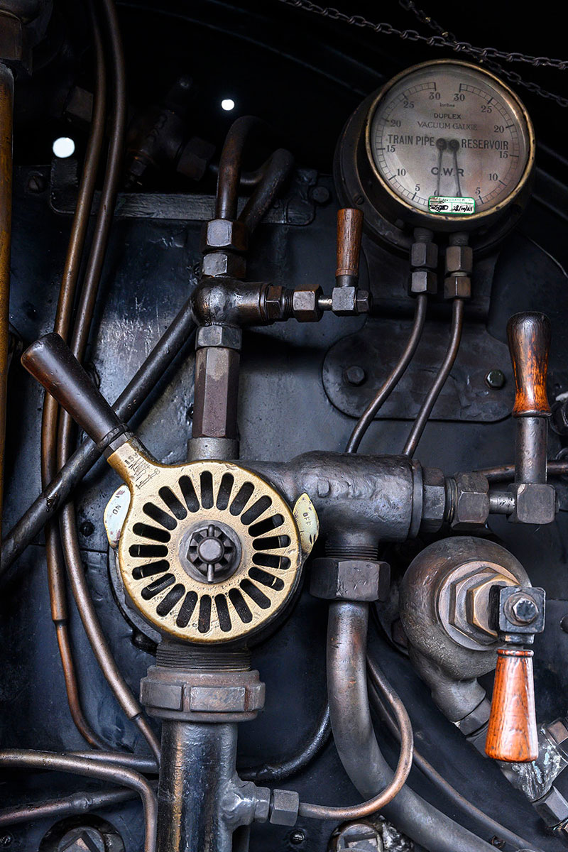
The actual valve fitted to No 4079 Pendennis Castle
The air pressure itself is produced by a compressor in the locomotive and is driven by whatever motive force is available. Most of the rest of the world used air brakes on steam engines and a steam powered pump was provided. Looking further afield, electric locomotives have an electrically driven compressor for example. Class 08 No 08 604 Phantom and class 14 No D9516 are both air brakes machines, but have vacuum systems fitted as well to allow them to operate stock so fitted.
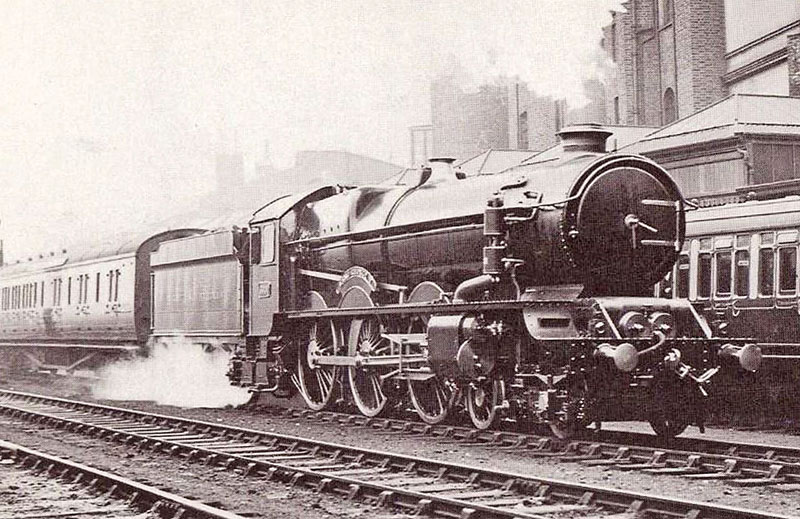
No 6000 King George V on 20 July 1927, fitted with an air brake pump in preparation for the locomotive’s visit to the USA later that year for the centenary of the Baltimore & Ohio Railroad
That’s a quick overview of the different types of brakes on the stock at Didcot and gives type a basic idea of how they work. There is a lot more nuance than this blog would suggest and I can take a deeper dive into various systems later on. At least you know how to stop now!
Just like me.
Stopping.
Writing the blog.
Now.
FRIDAY 15 SEPTEMBER
Personality Profiles – Isambard Kingdom Brunel
Yep, the big one! It goes without saying that this is a fairly important name in the history of both the Great Western Railway and the nation as a whole. Arguably the greatest engineer to ever work in the UK and a man of immense achievement that has caused him to be a household name long after his death. Clearly Going Loco isn’t going to be able to recount the entirety of his achievement in full – books have been dedicated to that sort of thing – but we can outline who he was and what he did. So, Brunel class 101. Let’s begin .…
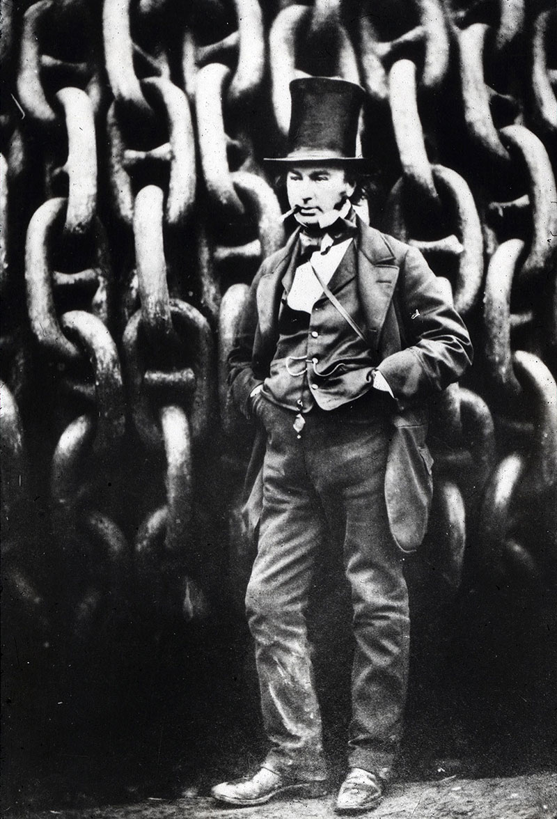
The ‘little giant’ with the large hat and large cigar, in front of large chains. Scanned from a BTF lecture transparency
The ‘little giant’ entered the world in his littlest form on 9 April 1806 in Portsmouth. His name comes from his parents. His dad was Marc Isambard Brunel who was a prominent French engineer who had fled France during the revolution of the late 18th century. His mum was Sophia Kingdom, a daughter of a contracting agent for the Royal Navy and British Army. His upbringing was not a wealthy one but he showed great talent from an early age. His father had taught him Euclidean geometry by the time he was eight and he was educated in both the UK and France, returning home in 1822.
The early project he and his father are most famous for is the first tunnel dug under the River Thames in London, between Rotherhithe and Wapping. This used a tunnelling shield to make its way through the unstable ground that London is built on. It was hard going and one collapse nearly cost Isambard his life but it was eventually completed in 1843, although was never a success financially. It is still in use, however, though as part of the East London Line which has now become part of the London Overground Network.
Before the completion of the Thames Tunnel, in 1833 Isambard was appointed as chief engineer to a new company that wanted to link Bristol to London with one of these new-fangled railways. The Great Western Railway as it was to become was one of the great works of the age. When you consider that he was looking to speeds not incomparable with some modern services, he was clearly going to design something special. He surveyed the entire route himself and made sure to pick one that was as flat and smooth as possible. This led to such derogatory names as ‘Brunel’s Billiard Table’ or ‘The Great Way Round’ being bestowed upon it. Brunel clearly knew what he was doing. In 1829, Stephenson’s Rocket locomotive was doing 30mph. By the time the first trains were running on the GWR, they were doing anything up to 60mph.
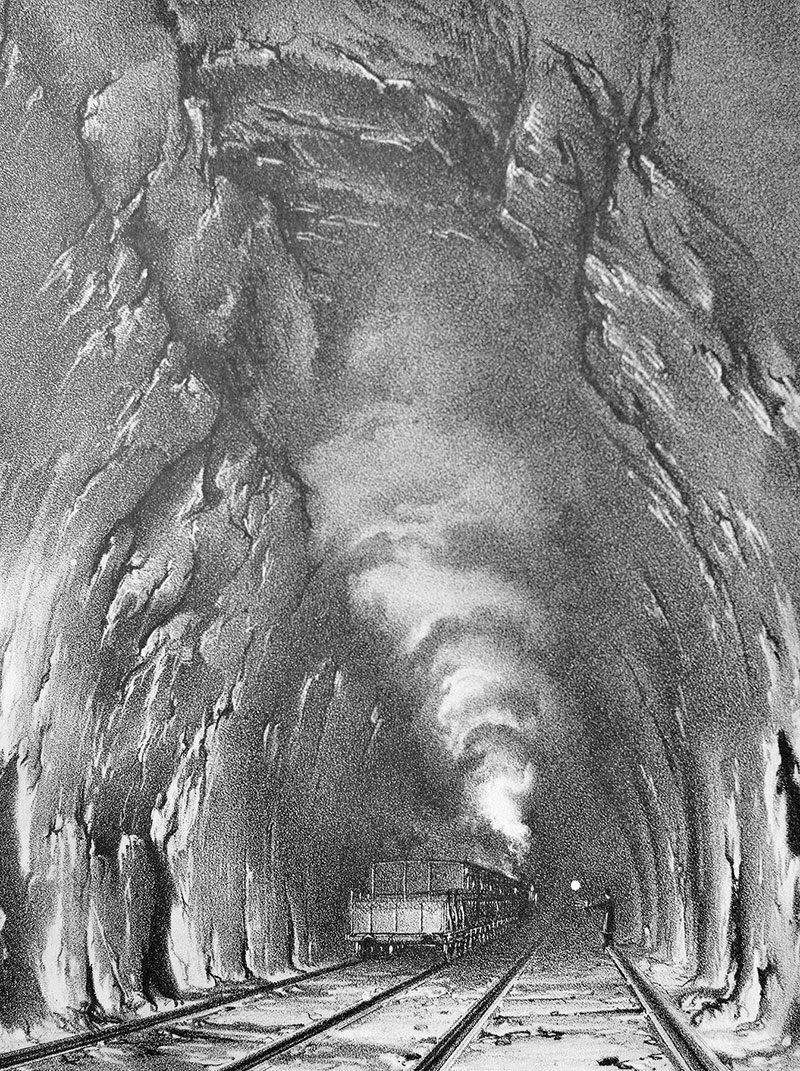
The interior of Box Tunnel from a J C Bourne lithograph
The speed of travel between London and Bristol went from 30 miles a day to 60 miles an hour. Brunel’s railway literally shrank Britain. Prior to the railway, every town had its own local time. The time difference between London and Bristol was about eleven minutes. This caused no end of confusion and as a result, time was standardised on to Railway Time (or London Time). A policy that we still use today.
It wasn’t just the speed of travel that made the GWR stand out. The civil engineering structures along it were mightily impressive too. The list of amazing works that are still in use today go on and on. Paddington Station, the elliptical brick arch bridge at Maidenhead, Box Tunnel, the Royal Albert Bridge at Saltash and so on and so on. He also decided to base the railway on a broad track gauge of 7’ 0¼” rather than the more usual 4’ 8½”. Brunel argued (quite rightly) that it made for more stable running at high speeds and that it increased the potential for carrying larger loads. It actually caused the GWR a great deal of issues later in its history, after Brunel had died, as it was non-standard. It eventually went the way of other superior but less popular formats* and the railway had to change to the smaller standard gauge. He also caused issues for another of his railways – this time the South Devon Railway. His plan here was typically forward thinking. I’ve covered the Atmospheric Railway before** but it really wasn’t a success .…
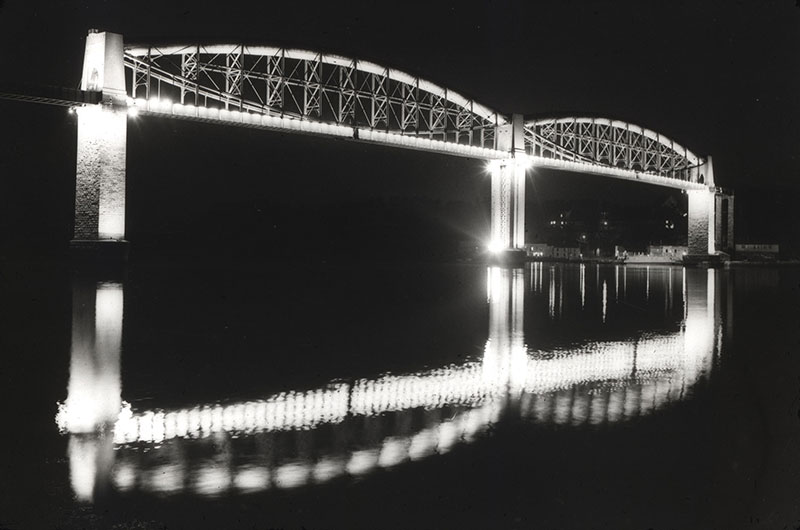
The Royal Albert Bridge floodlit for its centenary in 1959. Scanned from a BTF lecture transparency
Brunel married on 5 July 1836. His wife, Mary Elizabeth Horsley, was the daughter of a famous composer and organist William Horsley and was part of a renowned creative and artistic family. They were eventually to have three children and although he was always busy, he cherished the time he spent with them. One amazing tale of his ingenuity stems from a conjuring trick he was performing for them with a half sovereign coin. Whilst doing this, he accidentally inhaled it and it lodged in his windpipe. It was immensely painful but being a family of engineers, a coin removal solution was worked through. A specially designed set of forceps was the first try and this did not work. A special ‘Brunel shaking device’ was also tried but with little success. Marc Brunel eventually suggested strapping his son to a board, turning him upside down and shaking him, which resulted in the coin regaining its freedom! The very epitome of Victorian engineering problem-solving in many ways!
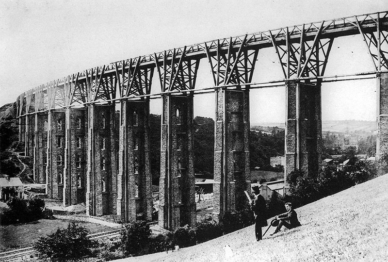
Moorswater viaduct was one of the Brunel timber structures designed by Brunel for the Cornwall Railway. It was replaced by a stone structure with the original pillars remaining beside it
Whilst the GWR is our favourite Brunel project (clearly!), the list of his other achievements is outstanding. International shipping saw him develop a series of three steamships that were capable of travelling across the Atlantic. Previous to Brunel it was thought that it wasn’t possible to carry enough cargo and fuel in the same ship to make steam propulsion profitable. The first in 1838 was designed to take the Great Western Railway and connect it with New York. Appropriately named PS Great Western she was a transport revolution and a sister, SS Great Britain*** was launched in 1843. This was the first ‘modern’ ship being made of a metal and having a screw propeller, not paddle wheels. His third ship, the PSS Great Eastern had much less success. This giant ship was intended to be able to travel between the UK and India or Australia without refuelling. Whilst technically it worked flawlessly, it ran over budget, and was delayed numerous times due to a series of technical issues. It did however have a huge influence on the world by laying transatlantic telegraph wires, linking Europe and North America reliably for the first time.
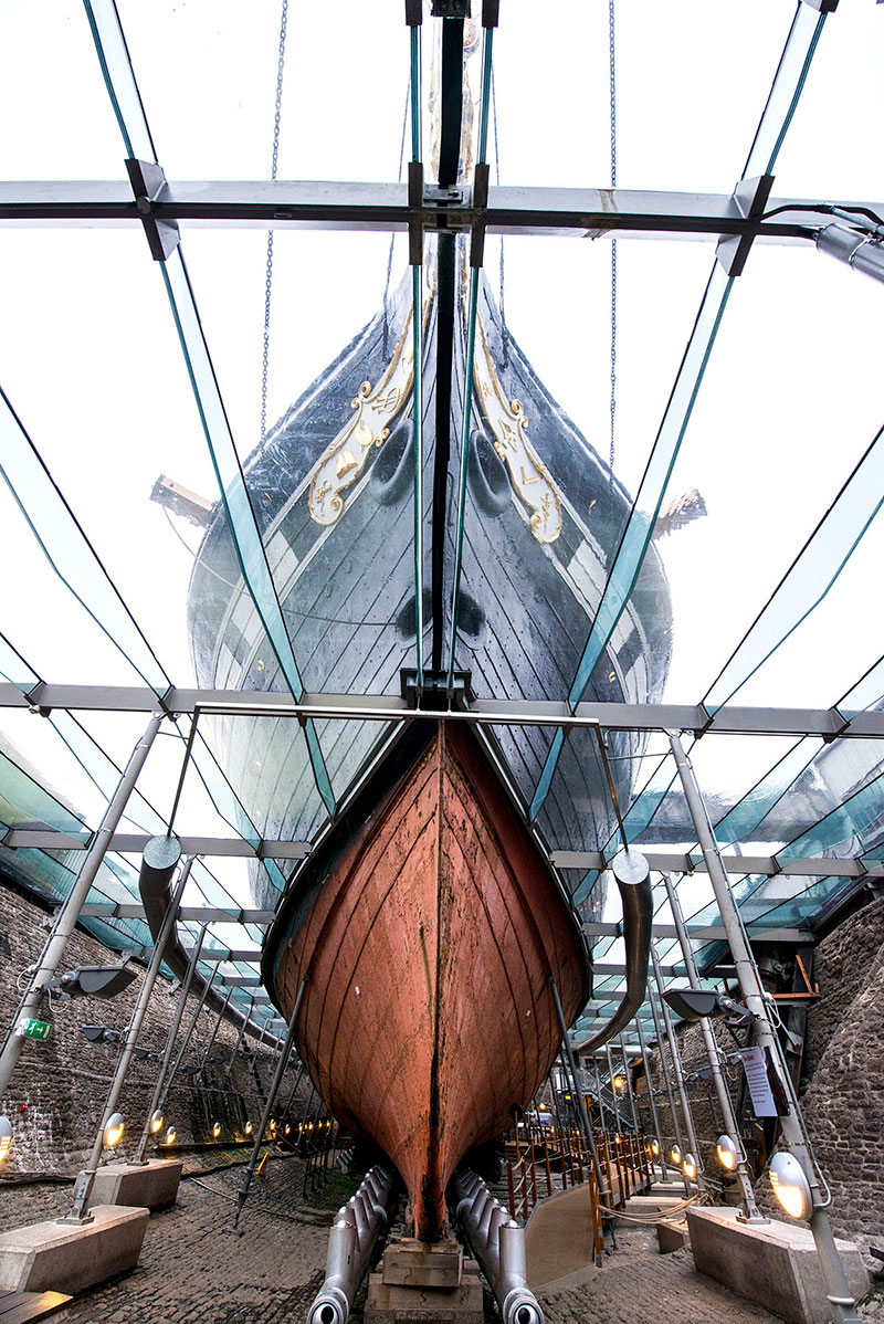
Brunel’s Great Britain preserved in her original dock at Bristol, with a glass roof representing sea level that protects the fragile lower part of the hull
An often overlooked but vital contribution to medicine was made with the help of Brunel. The so-called Renkioi Hospitals were designed in response to a plea by none other than the ‘Lady with the Lamp’ herself, Florence Nightingale. The Crimean war had erupted in 1854 and the British hospital for injured servicemen was set up in the old Turkish barracks in Scutari. Here the patients were contracting cholera, dysentery, typhoid and malaria as a result of the horrific conditions there. The War Office asked Brunel if he could assist by designing a prefabricated hospital to send to the Crimea. It took him and colleague William Eassie just five months to design, build, package and send a whole new hospital to them with excellent assembly instructions included. It included designs based on the need for hygiene as well as access to sanitation, drainage, ventilation and basic temperature controls to boot. It was assembled at Renkioi and the numbers speak for themselves. The hospital treated 1,300 patients and of those, only 50 passed away. The death rate at Scutari was ten times that figure .…
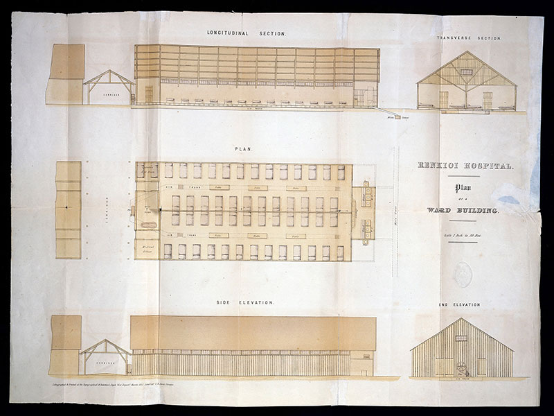
A drawing of one building of the Renkioi Hospital. The original is in the Wellcome Collection
Brunel was a textbook case of workaholic. He designed the Renkioi Hospital while building the PSS Great Eastern – 692’ long, 18,915 ton monster the like of which wasn’t seen again until the turn of the century. He was a heavy smoker, being partial to a large quantity of cigars every day. He also suffered with a kidney condition known then as Bright’s Disease but nowadays known as nephritis. This is an inflammation of the kidney and needless to say, I did look it up on Wikipedia but wished I hadn’t. He pretty much worked himself in to an early grave, and had a massive stroke while the preparations for the maiden voyage of the Great Eastern were being made on 5 September 1859. He clung on for ten days but the great man breathed his last on 15 September 1859 in Westminster, London. He is buried with many members of his family in Kensal Green Cemetery, London.
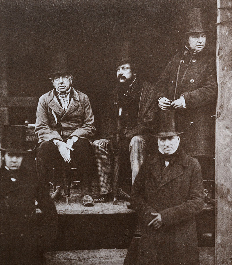
At the launch of the Great Eastern in 1857, Brunel is standing on the far right. Robert Stephenson, designer of the Rocket, is seated on the left
Brunel is today rightly remembered as one of the fathers of the modern age. He has been immortalised in everything from statues and names of places and buildings to stamps and coins. His tall hat has become visual shorthand for the very epitome of the Victorian-era gentleman. However, his influence on the world is still to be felt in most areas of our lives today.
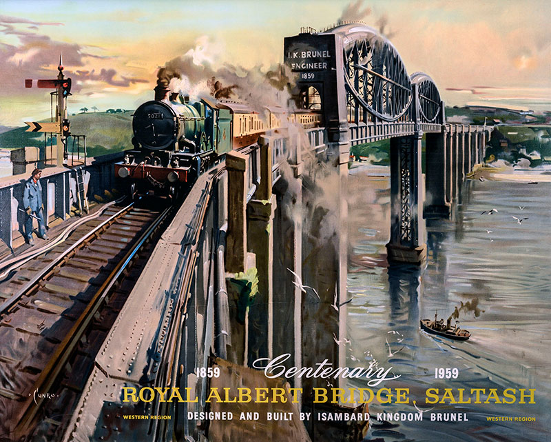
The Cuneo painting of the Royal Albert Bridge was issued as a poster for its centenary in 1959. Original poster in the Great Western Trust collection
Standardisation of time, national and international travel, and that’s without mentioning all the structures he engineered that are still about today. He had his flaws – don’t get him to design your railway locomotives. Don’t be a financial backer of this man’s schemes – he’s actually working about 50 to 100 years in the future and while his ideas are sound, he may well bankrupt you. However, on balance, he stands out as an utter genius and a total visionary in an era which has more than its fair share of people with that accolade. And is still remembered as such over 160 years from his death. That’s quite the record .…
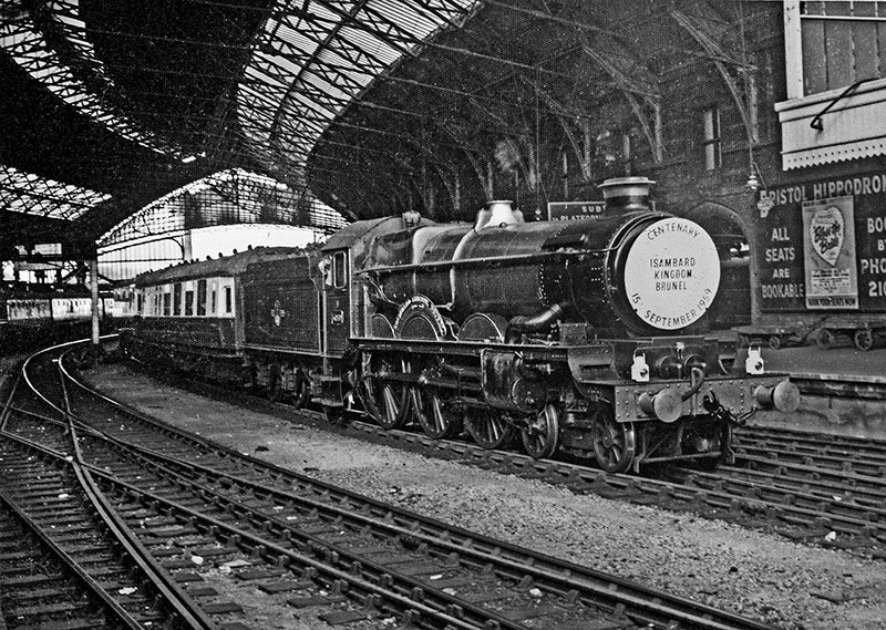
On 15 September 1959, a Brunel centenary ceremony was held in Bristol with the unveiling of a memorial tablet on Clifton Suspension Bridge. A party from London travelled to the ceremony on the 1.15 pm train from Paddington which was hauled by Castle class 4-6-0 No 5069 Isambard Kingdom Brunel bearing a full-size smokebox door headboard marking the event. This photograph shows the locomotive coupled to the Ocean Saloons which carried the party
* BetaMax video tapes anyone? Yeah, I know, I’m old .…
** Look at the blog Broad Gauge Banter Part 2 – This Train Sucks! on this page:
https://didcotrailwaycentre.org.uk/article.php/452/going-loco-march-2021/7e92640a116dc4d4f846270bb6a6cd4d
*** Now preserved in Bristol - well worth a look!
FRIDAY 8 SEPTEMBER
Fun, Fun, Fun With A Thirty One!
We’ve had an arrival at Didcot and it’s another one of those steam engines that burns the liquid coal. The other really strange thing about it is the ridiculously small water tank – it’s just marked as coolant and it doesn’t seem to come out going chuff as it goes along*. Curiouser and curiouser said your blogger .…
The locomotive in question is No. 31 270 Athena. The Class 31 is one of a number of diesel locomotive classes that came out of the somewhat ill-conceived BR Modernisation Plan of the 1950s. Part of the modernisation plan was the abolishment of steam traction. The idea was to give all locomotive manufacturers in the UK a chance to build prototype replacements for all the different types of steam locomotives then at work. Even if they hadn’t had much experience doing so .… This was called the Pilot Scheme and they were eventually gathered into a number of different power types. There were the shunters in two groups: below 300 horsepower (hp) and from 300hp – 799hp. You then had Type 1 (800hp – 1,000hp), Type 2 (1,001hp – 1,499hp), Type 3 (1,500hp – 1,999hp), Type 4 (2,000hp – 2,999hp) and finally Type 5 (3,000hp and above).
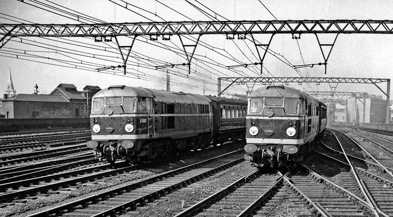
Two class 31s racing from London Liverpool Street towards Bethnal Green on 30 August 1958. On the left is the first of the class, No D5500, with the 11.12 from Liverpool Street to Gorleston Holiday Camp. On the right is D5506 on the 11.08 to Walton-on-Naze. Photograph by Ben Brooksbank
There were a number of issues with this. The financial losses of British Rail were mounting. The labour-intensive steam locomotive was not a good look in this climate, so the Pilot Scheme was accelerated. The result of this was those prototype diesel locomotives being ordered off the drawing board. En-mass. Untested. That went about as well as you’d think it did. They were also trying to fill roles on the railway that were fast becoming obsolete. Our very own Class 14 No 9516 being a prime example. An engine designed for short distance and branch freight workings – something that was on the way out, in favour of carrying fixed trains of a single bulk commodity.
Out of this mess, there actually came a few gems, some of which ended or will be ending their service lives in the 21st century. One of these stalwarts was the Brush** Type 2. The first engine – No D5500 – was completed in September 1957 and was handed to BR in October. The class made its debut into service in November. There were 263 built between 1957 and 1962 and were numbered D5500 – D5699 and then D5800 – D5862.
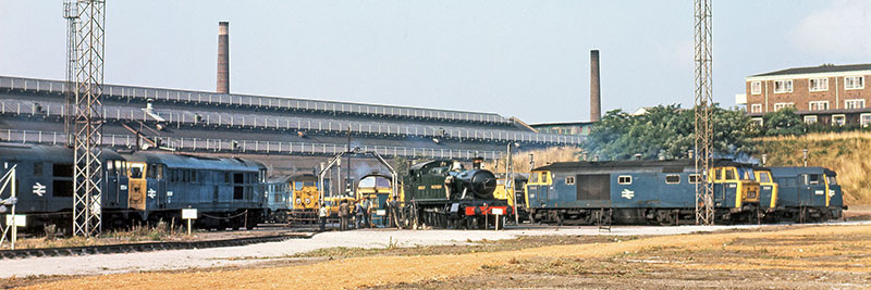
2-6-2T No 6106 on the turntable at Old Oak Common when she visited the open day there on 2 September 1972. The diesel locos surrounding her are, left to right, 5554 (31 136); 5539 (31 121); unidentified class 31; unidentified Western class 52; 5814 (31 414); Hymeks 7044 and 7001; 5682 (31 254) and an unidentified class 52. Great Western Society photograph
They were originally based around a Mirrlees 1,250bhp JVS12T engine and had Brush electrical equipment. As these power plants were somewhat unreliable, No D5677 was fitted with an English Electric 12CSVT which is a version of the engine used in the English Electric Type 3 in 1964. This was successful, and all the other locomotives were eventually so treated between 1965 and 1969. They are of an A1A-A1A wheel configuration. The letter stands for a powered wheel and the number stands for a non-powered or carrying wheel.
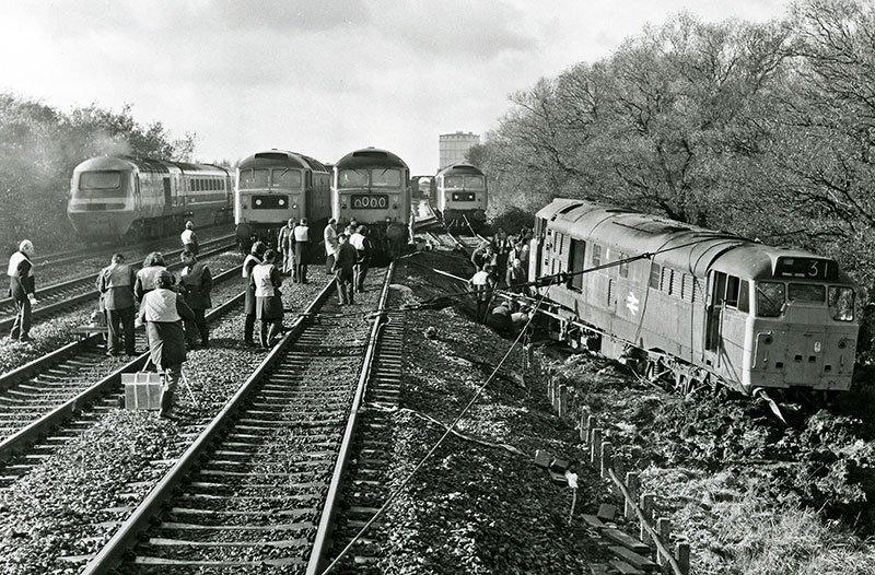
No 31 273, having taken a dive down the embankment near the Wharncliffe Viaduct in Hanwell on Hallowe’en evening 1977, was dragged back on the track three weeks later, on 20 November. Six class 47s, four sets of Kelbus block and tackle, and the ingenuity of British Rail engineers, ensured a successful operation. Some 18 months later we met 31 273 again, on 21 April 1979, when she hauled a GWS Vintage Train railtour from Paddington to Sheffield for electric haulage across the Pennines to Manchester. 31 273 was a complete failure at Fenny Compton on the journey home. Great Western Society photograph
A whole bunch of different adaptations were made over their lives and they were all given sub class designations under the Total Operations Processing System, or TOPS. This is a computer-driven system that dates from the late 1960s and remarkably remains in use in some form even today. So, those with the original engine were designated Class 30 but when re-engined, they were distinguished by being labelled as Class 31. The locomotives were renumbered from the previously mentioned series to Nos 31 001 to 31 970. The outline of the subclasses were as follows:
31/0
The original locomotives. They did not have the characteristic head code box above the front windows of the cabs and as a result gained the nickname ‘skinheads’! They had an unusual type of electro-magnetic multiple working equipment*** which made them non-standard and early candidates for withdrawal, which began in the late 1970s.
31/1
The first twenty of these were ‘skinheads’ but the rest were conventional with the what was to become standard head code box. They were all fitted with steam heating boilers. This was needed to interface with the steam-era coaching stock still in use at the time. These locos were all fitted with the much more common ’Blue Star’ electro-pneumatic multiple working gear. This made them far more compatible with other classes.
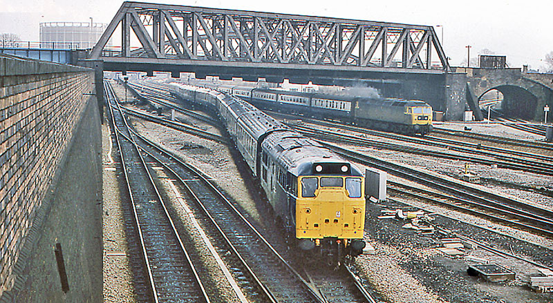
No 31 279 hauling empty carriage stock from Paddington to Old Oak Common on 18 March 1979. The girder bridge behind carries the West London Line. An express from Paddington hauled by a class 47 diesel is in the background. Photograph by Ben Brooksbank
31/4
These were conversions of the 31/1s to have electric train heating (ETH) equipment. This enabled them to haul more modern coaches but came at a price. The electric train heating pulled 330kW of electricity from the generator. This was approximately a third of the total power output and as the Class 31s were regarded as slightly underpowered to begin with, this clearly didn’t help .… On service trains, they were limited to about four or five coaches, otherwise they began to struggle.
31/5
It’s all to do with that electric train heating you know – these were previously 31/4s that had the ETH cable removed to prevent its use. The thinking here was that it made sure that they were available for freight work only and not capable of being ‘borrowed’ by the passenger train department(!). It also meant that the equipment wasn’t being used and therefore no longer had to be maintained, cutting costs. This was done in the late 1980s.
31/6
So, if you had the wires to take the ETH from an engine in front to the coaches behind, but didn’t have the equipment to provide ETH yourself, you are a 31/6. Only two were ever so converted during the early privatisation era.
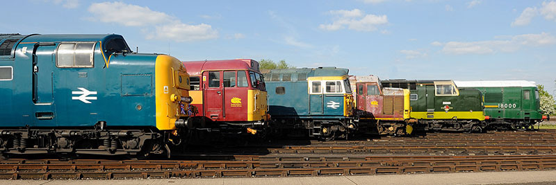
A previous visit of a class 31 to Didcot Railway Centre, at the diesel gala on 26 May 2013; left to right. Deltic class 55, 55 019 Royal Highland Fusilier; class 31, 31 466; class 33, 33 108; class 37, 37 521 English China Clays; Deltic class 55, 9009 Alycidon; and gas turbine 18000. Great Western Society photograph
The class 31s worked all over the network, one of the duties that they were first tasked with on the former GWR was the work once undertaken by the faithful pannier tanks – the movement of empty coaches in and out of Paddington station. They were used in a wide variety of different roles across the UK, including passenger, freight, engineering trains and so on and so on. A handful are still active in the network at the time of writing.
As a compliment to them, no less than 31 of these machines are in preservation up and down the country. One of which has come to live with us for a while at Didcot. No 31 270 is named Athena**** and is on extended loan from Colne Valley Diesels Ltd. She entered service on 1 June 1961. She was originally numbered No. D5800 and served faithfully for nearly forty years, being in passenger service as late as 20 November 1994. She was finally withdrawn from service on 30 May 2000. She has toured various galas as well as working at her home base at Peak Rail. She has received heavy mechanical maintenance at Nemesis Rail, Burton-on-Trent, before coming to Didcot.
She will remain in Regional Railways livery for the time being but may well have some work done to the bodywork while she lives with us. She will act as a backstop to provide us with a bit of flexibility in our diesel fleet and will no doubt be seen in action as soon as crew training is sorted out. So, if you want to see something a little different running at Didcot, keep an eye on our on-line loco roster for days when No 31 270 is working.
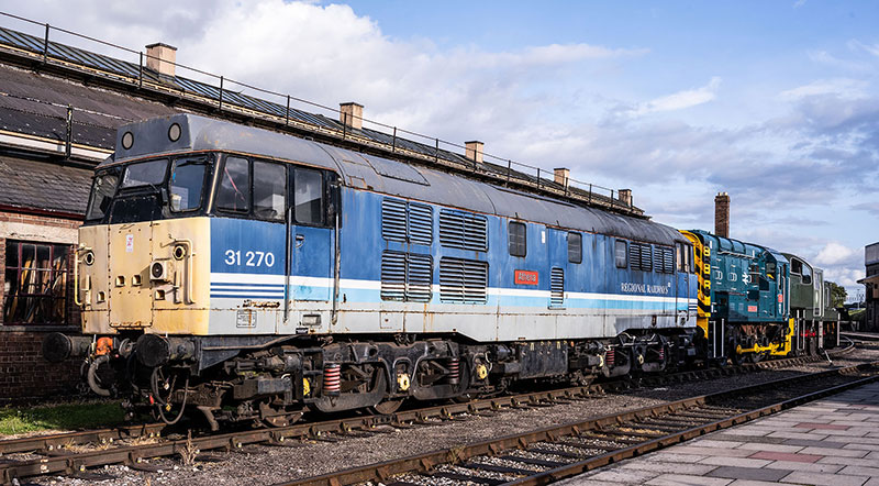
No 31 270 on 27 August 2023, soon after arrival for her stay at Didcot. Great Western Society photograph
* At least we HOPE it doesn’t .…
** A manufacturer and maintainer of locomotives and not something you sweep with! They were merged into the Wabtec in 2011 and the closure of their original premises at Loughborough was announced in 2021.
*** Multiple working equipment is used to control two or more locomotives by the use of the controls in just one of them. Our very own GWR diesel railcar No 22 has a system like this.
**** Greek Goddess of Warfare, Wisdom and Handicraft. Which is quite a diverse portfolio when you think about it. Combat, cogitation and crochet?
FRIDAY 1 SEPTEMBER
The Lost Cousins of No 2516
It’s been rather fun to delve into the missing links in the chain that leads to the Great Western Society collection at Didcot. Maybe this is the beginning of an August tradition? In the Steam Museum at Swindon slumbers the final survivor of a great and most remarkable type of humble goods locomotives – the Dean Goods. No 2516 represents a type that was built near the end of the 19th century and yet was used until the 1950s having served in two world wars, some even seeing action overseas.
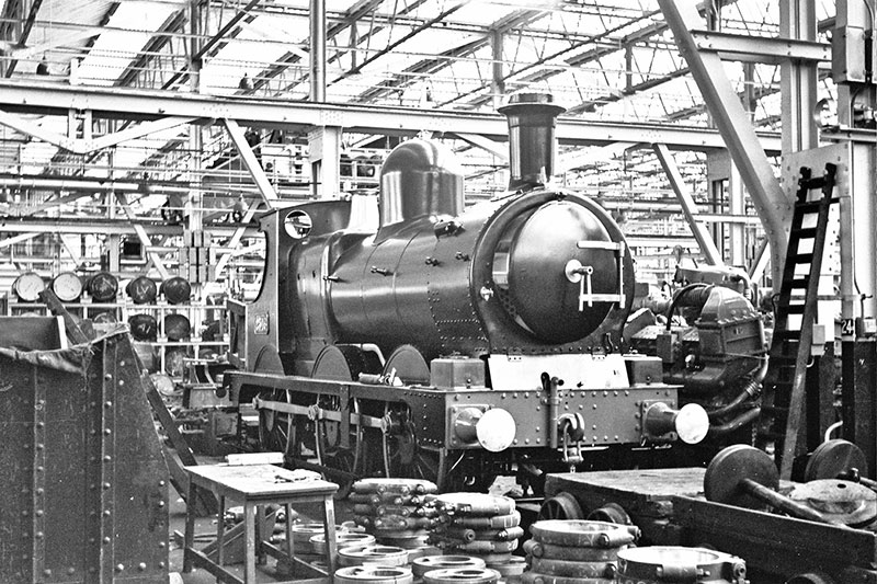
The one surviving Dean Goods 0-6-0, No 2516, under restoration at Swindon in 1962 before moving into the original GWR Museum. Photograph by Mike Peart
What is less well known is where the Dean Goods themselves came from. They were a development of a much earlier design by the most poorly-represented chief mechanical engineer, Joseph Armstrong. Armstrong has no surviving examples of his locomotive designs. Ok, neither does Gooch, but there are at least three replicas of his work, two of which (Iron Duke and Firefly), have operated in living memory. Even William Dean has No 2516 and (technically*) Dukedog No 9017. City class No 3440 City of Truro, although being a Churchward design, also gives us a really good idea of how many Dean designs looked and operated, due to her 1903 build date. So, we are staring into us one of steam preservation’s ‘black holes’. A truly lost age .…
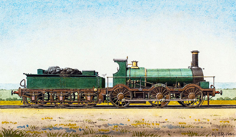
Europa, one of Gooch’s broad gauge Standard Goods engines built in 1853, from a painting by P J T Reed in the Great Western Trust collection
Joseph Armstrong and his brother George both worked as engineers for the Great Western Railway. There were two loco works at this time, the one at Swindon we are all familiar with and the other at Wolverhampton. Due to the two different gauges that the GWR worked with at the time** Swindon did the designs for the broad gauge and Wolverhampton did the work for the standard gauge. After Gooch retired from GWR engineering in 1864, Joseph moved to the top post at Swindon. Both he and later Dean were forced to deal with the decline of the broad gauge and although the final transition was done by Dean, it began with the Armstrong brothers.
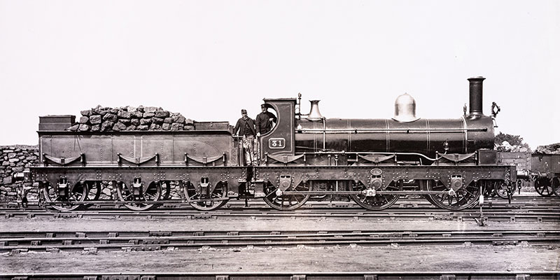
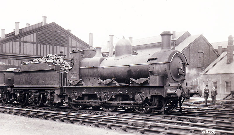
Armstrong Standard Goods No 31, built in February 1872. Photograph in the Great Western Trust collection
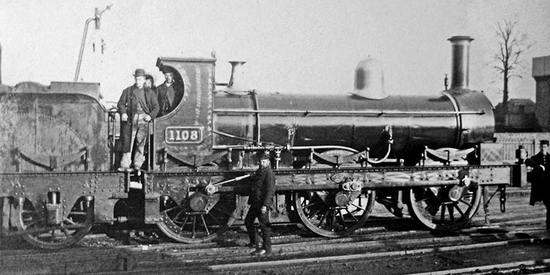
Armstrong Standard Goods No 1108, built in April 1871. Photograph from Trainiac on Flickr, Creative Commons
The 0-6-0 tender engine was the standard goods locomotive on Britain’s railways for the vast majority of the steam era. The first well known example being that of the Royal George, built by Timothy Hackworth for the Stockton & Darlington Railway in 1827. Preserved at the Darlington Railway Museum is another 0-6-0 of 1845 called Derwent. We also think of standardisation of being the province of Churchward from the early years of the 20th century, but there were large batches of locos built with a mind to this idea quite early on too. Daniel Gooch designed and built 102 of the Ariadne/Caliph class of 0-6-0 tender engines in 1852. These were broad gauge engines and are also known as the ‘Standard Goods’.
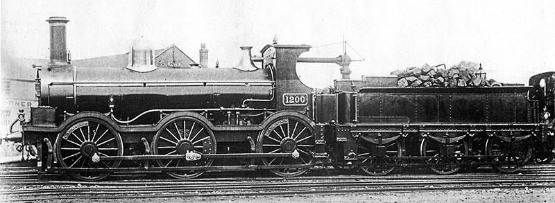
Armstrong Standard Goods No 1200, built in May 1876 and converted to broad gauge in February 1887. She was converted back to standard gauge in June 1892. Photograph from Trainiac on Flickr, Creative Commons
In 1866, the first of the design we are interested in today was completed. Armstrong’s design was in many ways a development of Gooch’s ‘Standard Goods’ and were differentiated from them by being called the 388 Class or Armstrong Goods. The new type shared a fair bit with the Gooch engines. They both had 5’ diameter driving wheels and cylinders that were 17” in diameter with a 24” stroke. They had their cylinders, connecting rods and valve gear between the frames and were a compact and light design. This gave them a ‘go anywhere’ capability and they quite often did! The biggest and most obvious difference between the two was that the earlier machines were broad gauge engines and had inside frames. The Armstrong engines had outside frames with the axle boxes on the outside of the wheels and the cranks and coupling rods on the outside of them.
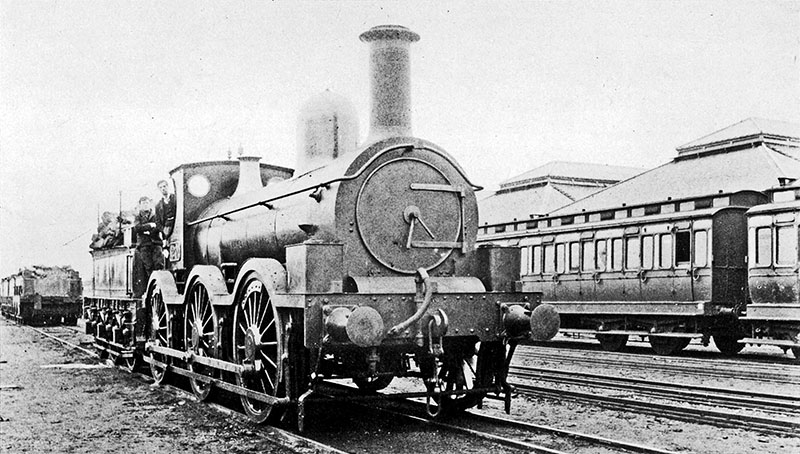
Another view of No 1200, showing how the broad gauge wheels outside the frames altered her appearance. Note how the broad gauge tender is much wider than the cab of No 1200. Photograph in the Great Western Trust collection
There were a total of 310 of these engines built in no less than 16 batches that were finally completed in 1876. The last of the broad gauge Gooch Goods went in 1883.*** To cover their end and to allow services to continue on the broad gauge until that came to an end, 20 Armstrong Goods machines were converted to a broad gauge configuration from 1884. They were all converted back when the broad gauge ended in May 1892. Clearly this contingency was built in to their design – good thinking, right? Apart from that, they served out the majority of the 19th century fairly unaltered. The usual variety of chimney fitments and various minor details changed but basically they were the same as they were designed. One thing that you can see if you look at photos of them is the emergence of strengthening plates around the locomotive axle boxes as time went on. This was a common fatigue point for all outside-framed engines it would seem, as it was a fairly typical modification.
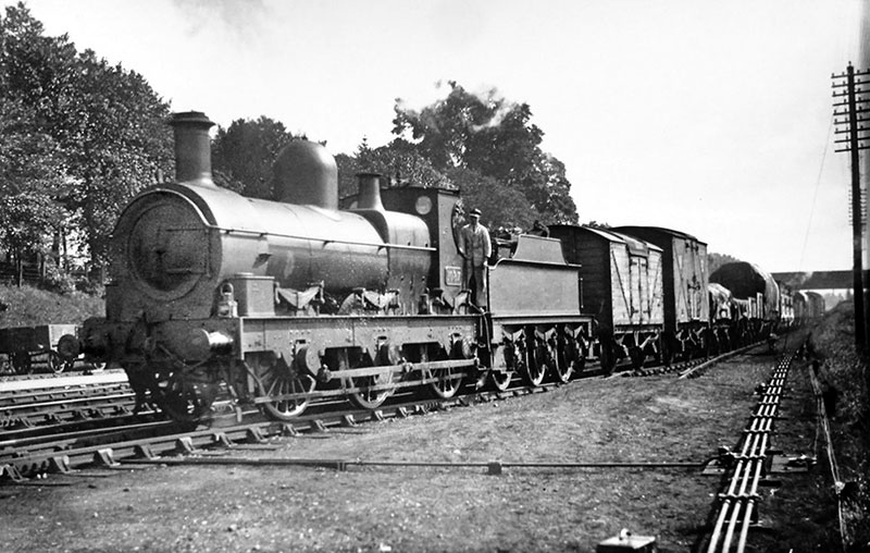
Armstrong Standard Goods No 1087, built in October 1870. In this view the locomotive is fitted with a Belpaire firebox boiler, which happened in February 1908. Photograph from Trainiac on Flickr, Creative Commons
Towards the end of the Dean and beginning of the Churchward era, they were some of the first locomotives on the GWR to receive the new squarer and efficient Belpaire style firebox as opposed to the round topped version they were built with. This happened as early as 1901, before members of the Dean Goods class even got a look in. A longer smokebox is also evident on some engines, due to the experimental nature of the technology at the time. A mix of boiler and smokebox**** shapes and so on were seen moving forward. From 1911, 60 members of the class were even treated to superheated boilers, making them even more efficient. More modern Dean era tenders were also allocated to some of the engines as well and this makes them look like outside framed versions of the Dean Goods class and probably causes confusion as a result. Despite all these updates on offer, many were scrapped without receiving any of them. The withdrawals of the 388 class really took off in the 1920s and the final one, No 1195, was withdrawn in October 1934.
Armstrong Standard Goods No 22, built in January 1876. This photograph was taken at Swindon, after January 1911 when she was fitted with a Belpaire firebox boiler. Photograph in the Great Western Trust collection
Here’s a thought. We all know that the Dean Goods went to war in both WWI and WWII, being exported to various parts of the world to help keep railways near combat zones running. Well, the Armstrong Goods served in WWI too. In 1916, six of them were sent to Serbia. Only two of them made it home again some time in 1921. There was another batch of sixteen that were sent to Salonica in 1917. Eight of them operated there. Four of them were adopted by the local Ottoman Railways and four more were sent home again, also in 1921. Which means there are holes in the record. It is almost certain that those left in Serbia and Salonica were scrapped many years ago but sixteen were sent in the second batch and we’ve only accounted for eight.
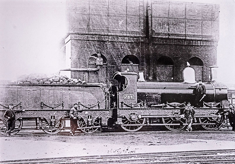
Armstrong Standard Goods No 784, built in August 1873, photographed at Didcot about 1890. This locomotive has been identified as one of the eight on a ship which was sunk in 1917 en route to Salonica. Photograph in the Great Western Trust collection
Well, the other eight were on a vessel that was lost at sea. They went down with their ship according to some reports, in the English Channel. Which means that there is the outside chance that their remains are still down there at the bottom of the sea. Forgotten and silent in the darkness. IF they are still down there and IF they are still in a recognisable state, this means that there are more existing locomotives designed by Armstrong than those designed by Gooch and Dean combined .…*****
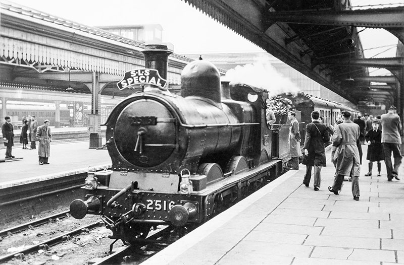
Dean Goods No 2516, the last survivor of all the Armstrong and Dean 0-6-0s, photographed by Michael Mensing at Birmingham Snow Hill on 21 May 1955, about to haul the Stephenson Locomotive Society’s West Midlands Railtour
Our archives have drawn a blank as to the ship, the action and location of this wreck. Some sources suggest a sinking date of May 1917. Over to Internet land on this one I think.
* Although the Dukedog class is attributed to Collett as their rebuild was done in the 1930s, the Duke and Bulldog classes that had their components combined to make them were both Dean designs.
** The rails on Brunel’s broad gauge track were 7’ 0¼” apart and the standard gauge that eventually replaced it is 4’ 8½”.
*** Except for Europa (numbers were not given to many broad gauge engines, just names), which was extensively rebuilt and retained until the end of the broad gauge in May 1892.
**** The smokebox was removed with the boiler when they were removed at overhaul. This could mean the chimney too so this is how quite a bit of variation occurs in all standard GWR. classes. Look at pictures of the same engines at different times and you will start to notice it!
***** There are SO many problems about this being even a remote possibility. There’s the effect that being in the sea for over a century may well have had on them. Damage caused by the action that sunk the ship, damage caused by the sinking itself. Has the wreck been salvaged? Has the wreck received damage through the weather? Then there’s the issue that the wreck would potentially be regarded as a war grave so that would make it a no-exploration area. Nice to imagine them still being around though isn’t it?!
Didcot Railway Centre Newsletter
Stay up to date with events and what's going on at Didcot Railway Centre.
You may unsubscribe at any time. We do not share your data with 3rd parties.